Gears, as the basic and key components in the mechanical field, play a vital role in various mechanical equipment with their unique structure and function. This article will discuss the processing technology of gears in depth, in order to provide reference for professionals in related fields.
Basic structure and function of gears
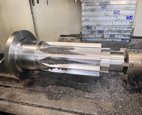
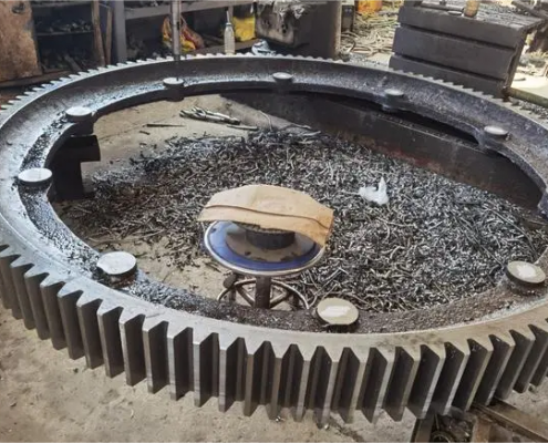
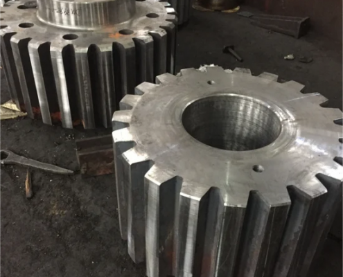
Gears are mechanical parts with toothed shapes, which transmit power and motion by meshing with each other. Gears are composed of two major parts: the ring gear and the wheel body. Gears with different functions will be different in design, but the basic structure remains the same. Common types of cylindrical gears include disc gears, sleeve gears, internal gears, shaft gears, fan gears and racks, among which disc gears are the most common due to their wide application.
Precision requirements for gears
The manufacturing accuracy of gears directly affects the working performance, load-bearing capacity and service life of mechanical equipment. According to the conditions of use, gear transmission needs to meet the following accuracy requirements:
1. Motion accuracy: ensure that the gears can accurately transmit motion, maintain a constant transmission ratio, and limit the angular error within a certain range.
2. Working stability: The gears are required to be stable during movement, reduce impact, vibration and noise, and limit the change of angular error in a short period.
3. Contact accuracy: Ensure that the gears have uniform contact on the tooth surface when transmitting power to avoid premature wear caused by uneven load distribution.
4. Tooth side clearance: Leave an appropriate gap between the non-working tooth surfaces to store lubricating oil and compensate for dimensional changes and processing and assembly errors.
Material selection of gears
The material selection of gears has a direct impact on their processing performance and service life. Common gear materials include medium carbon steel, low and medium carbon alloy steel, and for gears with higher requirements, special materials such as nitrided steel may be selected. Non-power transmission gears can also be made of cast iron, cloth-reinforced bakelite or nylon.
Heat treatment process of gears
The heat treatment process in gear processing is mainly divided into two types:
1. Blank heat treatment: Normalizing or tempering treatment is performed before and after the gear blank is processed to eliminate residual stress, improve the machinability of the material, and improve the mechanical properties.
2. Tooth surface heat treatment: After tooth processing, carburizing quenching, high-frequency induction heating quenching and other processes are often used to improve the hardness and wear resistance of the tooth surface.
Gear tooth processing method
Gear tooth processing is the core link of gear processing, including forming method and development method. The forming method uses forming tools that match the tooth shape, such as milling, pulling and forming grinding. The development method is that the gear tool and the workpiece perform development movements according to the meshing relationship, such as hobbing, gear shaping, shaving, grinding and honing.
Tooth end processing
Tooth end processing includes rounding, chamfering, chamfering and deburring. These processes can reduce collision, remove sharp edges and burrs, and improve the meshing performance of gears.
Gear precision requirements
The manufacturing accuracy of gears directly affects the working performance, load-bearing capacity and service life of mechanical equipment. According to the conditions of use, gear transmission needs to meet the following precision requirements:
1. Motion accuracy: ensure that the gear can accurately transmit motion, maintain a constant transmission ratio, and limit the angular error within a certain range.
2. Working stability: require the gear to be stable during movement, reduce impact, vibration and noise, and limit the change of angular error in a short period.
3. Contact accuracy: ensure that the gear tooth surface contacts evenly when transmitting power to avoid premature wear caused by uneven load distribution.
4. Tooth side clearance: leave an appropriate gap between non-working tooth surfaces to store lubricating oil and compensate for dimensional changes and processing and assembly errors.
Material selection of gears
The material selection of gears has a direct impact on their processing performance and service life. Common gear materials include medium carbon steel, low and medium carbon alloy steel, and for gears with higher requirements, special materials such as nitrided steel may be selected. Non-power transmission gears can also be made of cast iron, cloth-reinforced bakelite or nylon.
There are two main types of heat treatment processes in gear processing:
1. Heat treatment of blank: Normalizing or tempering treatment is performed before and after gear blank processing to eliminate residual stress, improve material machinability, and improve mechanical properties.
2. Tooth surface heat treatment: After tooth shape processing, carburizing quenching, high-frequency induction heating quenching and other processes are often used to improve the hardness and wear resistance of the tooth surface.
Processing process of spur gears
The processing process of high-precision gears includes blank forging, heat treatment, profile processing, tooth surface processing, chamfering, deburring, high-frequency quenching, key slot insertion, grinding and other steps, each of which has an important impact on the performance of the final gear.
Gear processing process analysis
In the process of gear processing, the selection of positioning reference, processing of gear blanks, and processing of tooth ends are all key links. Correct positioning reference can improve production efficiency and processing quality, and the processing of gear blanks provides the necessary reference for subsequent tooth surface processing and testing.
Through a comprehensive analysis of the gear processing technology, we can better understand the complexity and sophistication of gear manufacturing, and how to ensure the performance and quality of gears through precise process control. In actual production, every detail cannot be ignored, only in this way can high-quality gears that meet the requirements be manufactured.